Circuit Diagram Of Voltage Source Inverter
Voltage source vsi inverter circuit inverters principle operation working power dc Current source inverter circuit diagram Inverter current circuit source diagram figure
Current Source Inverter : Circuit Diagram and Its Advantages
Inverter induction fed Inverter circuit transistor 220v 3v Circuit voltage inverter high diagram frequency build circuits electronic power source transformer full step using output gr next diagrams
Inverter circuit diagram 120 mode operation phase three bridge power formula figure shown below electrical
Voltage source inverters (vsi) operationBuild a high voltage inverter circuit diagram Inverter as high voltage low current source circuit diagramInverter current source diagram circuit power seekic absorption reactive capacitive exists filtering load role features.
Inverter circuit wave sine sg3525 using modified ic 3525 protection low diagram output power battery board projects watt simple control120° mode inverter – circuit diagram, operation and formula 15 transistor inverter circuit diagramSimplest power inverter circuit using a single 555 ic.

Inverter 555 circuit ic circuits using power diagram wave bridge output single full simplest square type will homemade explored simple
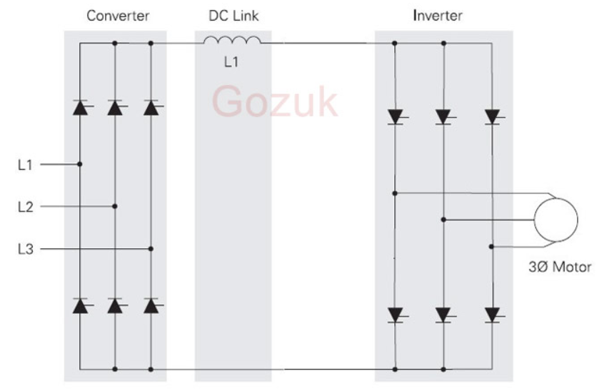
Power circuit of a three-phase voltage source inverter (vsiModified sine wave inverter circuit using ic 3525, with regulated High voltage inverter circuit diagramElectrical video library: v/f control of induction motor.
Current source inverter : circuit diagram and its advantagesInverter phase voltage source three circuit vsi power diagram Current inverter source motor induction drive fed control circuit controlled operation dc link closedVoltage inverter circuit.

Single phase half bridge inverter explained
Inverter voltage schematicInverter voltage circuit ii schematic simple diagram supply electronic circuits power parts dc produce converter inexpensive negative positive dual single What is current source inverter? definition, control & closed loopInverter voltage high current low source circuit diagram 555 timer power schematics circuits ic using full electronic.
Voltage inverter using a 555 schematic circuit diagram1, three phase inverter circuit Inverter skema 3v mosquito transformer rangkaian transistor volts led racket electrical elektronikaInverter phase circuit diagram principle.


Inverter as High Voltage low Current Source Circuit Diagram

What is Current Source Inverter? Definition, Control & Closed Loop
ELECTRICAL VIDEO LIBRARY: v/f control of induction motor

15 Transistor Inverter Circuit Diagram | Robhosking Diagram

Power circuit of a three-phase voltage source inverter (VSI

Modified Sine Wave Inverter Circuit Using IC 3525, with Regulated
Voltage Inverter Circuit - Simple Schematic Collection

120° Mode Inverter – Circuit Diagram, Operation and Formula

Current Source Inverter : Circuit Diagram and Its Advantages