Circuit Diagram To Verilog
Multiplexer mux verilog logic 8x1 multiplexers implemented simplicity Solved a) write a verilog module for the circuit below using Multiplexer logic mux 2x1 verilog part15 ares
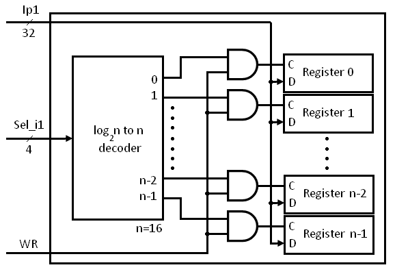
Verilog for Beginners: Register File
Verilog (part 1): example dataflow and structural description Getting started with the verilog hardware description language Verilog circuit module code write below style using file structural separate turn create transcribed text show xy
An introduction to verilog
Verilog reset dff synthesis module circuit schematic sync modulesSolved 2. write the verilog code, complete the timing Schematic verilog circuit vhdl pyroelectro tutorials introduction full introVerilog language hardware description example code started getting hdl introduction quick articles shown.
Verilog for beginners: register fileTiming verilog synchronous asynchronous write Verilog code for full subtractor using dataflow modelingSubtractor verilog dataflow modeling adder equations circuitikz technobyte.
Register file verilog block diagram operation write beginners figure
2x1 mux logic diagram : verilog code for 2:1 multiplexer (mux)Verilog dataflow structural example description part Verilog moduleVerilog code for 8:1 multiplexer (mux).
.


Verilog module

Getting Started with the Verilog Hardware Description Language

Solved 2. Write the Verilog code, complete the timing | Chegg.com

Verilog Code for Full Subtractor using Dataflow Modeling

Verilog for Beginners: Register File

Solved a) Write a Verilog module for the circuit below using | Chegg.com

Verilog code for 8:1 Multiplexer (MUX) - All modeling styles

Verilog (Part 1): Example Dataflow and Structural Description - YouTube